Is Drywall a Continuous Air Barrier

by John Chamberlin, MBA
According to the U.S. Department of Energy (DOE), buildings account for 39 percent of total energy use in the United States.1 Efforts to reduce this consumption is reflected in recent changes to building practices and codes.
For example, the DOE has mandated all states update their commercial building codes to meet or exceed American Society of Heating, Refrigerating, and Air-conditioning Engineers (ASHRAE) 90.1-2010, Energy Standard for Buildings Except Low-rise Residential Buildings, by October. Two key requirements of ASHRAE 90.1-2010 are continuous insulation (ci) and a continuous air barrier.
ASHRAE 90.1 defines continuous insulation as "insulation that is continuous across all structural members without thermal bridges other than fasteners and service openings." Meanwhile, continuous air barriers are defined as "the combination of interconnected materials, assemblies and sealed joints and components of the building envelope that minimize air leakage into or out of the building envelope."
With these requirements and definitions in place, compliance with ASHRAE 90.1-2010 should be easy. However, this may not be the case.
![This map shows the U.S. Climate Zones based on 2009 International Energy Conservation Code (IECC). [CREDIT] Data courtesy Building Energy Codes Resource Center, Pacific Northwest National Laboratory, U.S. Department of Energy](http://www.constructionspecifier.com/wp-content/uploads/2014/05/CS_October2013_HR-25-1000x534.jpg)
Why choose continuous insulation and air barriers?
The biggest problem with many insulated buildings involves thermal bridging. These occur when poor thermal insulator materials meet, creating the path of least resistance for heat to pass through.
An easy example of thermal bridging would be studs in a building's wall. Even though these studs typically have fiberglass batt insulation between them, the insulation does nothing to reduce the transfer of heat through the stud. Insulation materials include a nominal R-value, which is a measure of the material's ability to retard heat flow. In theory, a wall assembly constructed with an insulating material of a certain R-value would have a minimum of that material's R-value as an assembly. However, due to thermal bridging, the assembly's R-value may be much lower than the R-value of the insulating material itself. This has led to the concept of an assembly's 'effective' R-value versus its 'nominal' one.
According to studies conducted by the Oak Ridge National Laboratory (ORNL), thermal bridging in metal frame construction reduces the insulating performance of a wall assembly by 40 to 60 percent.2 For example, a 152-mm (6-in.) metal stud wall assembly including R-19 fiberglass batt insulation may only have an effective R-value between R-8 and R-11. Heating systems for buildings are often designed based on the assembly's nominal R-value, so in many cases unplanned for energy may be expended to heat a structure's interior. This is where continuous insulation comes into play.
ASHRAE now requires minimum continuous insulation R-values for buildings based on the climate zones in which those buildings reside. The International Energy Conservation Code (IECC) has identified eight unique climate zones throughout the United States (Figure 1). These zones are determined based on the region's average temperature, humidity level, and moisture level.
Continuous insulation on an assembly's exterior, either by itself or in conjunction with interior insulation, is the most economical and efficient way of achieving highly effective R-values. Since ASHRAE 90.1 requires continuous insulation be exempt of thermal bridges, its nominal R-value should be much closer to the effective R-value of the assembly.
Another major cause of energy consumption is air infiltration and exfiltration. Two of the major air pressures on buildings causing infiltration and exfiltration are wind pressure and stack pressure.
Wind pressure on buildings may have a serious effect on energy and moisture-related air leakage. Since wind pressure is not uniform across a building face, the higher up on a building, the higher the pressure is likely to be, especially as the building rises above objects that might restrict the wind's flow. Wind pressure pressurizes a building positively on the side it is hitting, but as the wind goes around the corner of the building, it speeds up. This causes the pressure to decrease, and change from positive to negative. These changes in pressure can affect how water moves around the building, especially at corners where water may enter the wall if there is an opening at a joint in the cladding. This phenomenon is known as 'wind wash'—its effects can be avoided as long as the air barrier is intact at the corners.
Stack pressure occurs when there is a difference in atmospheric pressure at the top and bottom of a building. This difference is the result of a variance in temperature at the top and bottom, causing varying weights of the columns of air inside the building compared to outside. In climates where the interior is heated, stack pressure may cause air infiltration at the bottom of a building and exfiltration at the top. In climates where the interior is cooled, exfiltration may occur at the bottom and infiltration at the top. Stack effect can be controlled by designing airtight vestibules, closing off openings (i.e. mechanical penetrations) between floors, and sealing vertical shafts within the building.
Air barrier systems help control air infiltration and exfiltration in buildings. These systems accomplish this by sealing joints, penetrations, and openings to create an airtight assembly. This, combined with venting and compartmentalizing, allows pressure to equalize between the interior and exterior of a structure. Without these differentials, air infiltration and exfiltration is restricted.
Air barrier systems should meet three key criteria:
- They should be continuous to not allow opportunities for air leakage.
- They should be structural, or in other words, permanently secured to the supporting structure. (Air barriers must be able to withstand wind pressure, stack pressure, and any pressure caused by mechanical effects, and ultimately transferred to the structure. If not a permanent part of the structure, air barriers may tear or displace under stress.)
- Air barriers must be durable. (They are typically installed behind a building's cladding and may require removal of the cladding for any type of maintenance or repair. For this purpose, a highly durable air barrier will always be preferred so maintenance can be avoided.)
Benefits of continuous insulation and air barriers
A study conducted by Morrison Hershfield, "Energy Conservation Benefits of Air Barriers," focused on the inclusion of both continuous exterior insulation and a continuous fluid-applied air barrier. Using 3D modeling, a prototype medium three-story office building was proposed for Dallas, Seattle, and Toronto climates. Baseline case buildings were set up to meet the minimum requirements of ASHRAE 90.1-2007 for newly constructed buildings.
According to the report:
Heating, cooling, lighting, and interior equipment energy consumption were modeled for each load case at 10-minute intervals and the results are summarized on a monthly usage basis in units of kilowatt hours (kWh). This data was then used to calculate energy savings over the base case, and an annual carbon equivalent was calculated based on the annual heating and cooling costs.3
The modeling determined that in terms of energy efficiency, the inclusion of a continuous air barrier actually had a greater impact than the continuous insulation. Annual energy cost savings ranged from $5000 to $19,000, compared to the baseline building which included continuous insulation by itself. Also, there was a diminishing return in energy cost savings as the R-value of the continuous insulation was increased.
The challenges with continuous insulation
The difficulty that arises with continuous insulation is ironically similar to the phenomenon that makes it necessary in the first place. The definition of continuous insulation explains it must be "continuous across all structural members without thermal bridges other than fasteners and service openings."
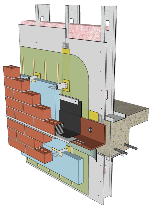
In this case, 'fasteners' refers to materials such as nails and screws. What this definition does not account for are common details such as ties and shelf-angles in masonry construction or clips and z-grits (i.e. horizontal structural member providing lateral support to the wall panel) in non-masonry cladding assemblies.
In a recent paper prepared by RDH Building Engineering Ltd., entitled "Thermal Bridging of Masonry Veneer Claddings and Energy Code Compliance," 3D-thermal modeling was used to determine the effects these types of details might have on the effective R-value of a wall assembly including continuous insulation. This value would change based on the actual construction assemblies and structure size. According to RDH:
metal cladding support connections occupying less than 0.5 percent and even less than 0.05 percent of the wall's surface area can have a profound impact on effective R-values (i.e. anywhere from 10 percent to greater than 50 percent).4
Using masonry construction as an example, RDH goes on to explain different types of masonry ties (e.g. steel versus fiber) and various backup materials (e.g. wood stud, concrete, or steel backup) also have an impact on the degree of thermal bridging that may take place.
Due to their low insulative value, steel masonry ties may reduce the insulation effectiveness by five to eight percent, depending on the type of steel and backup materials. Even more impactful, direct attached masonry shelf angles may reduce the effective R-value by 40 to 55 percent in conjunction with typical exterior insulation thicknesses and steel masonry ties.
Another study by Morrison Hershfield, "Thermal Performance of Building Envelope Details for Mid- and High-rise Buildings," looked at 40 common building design envelope details and again used 3D modeling to determine the effect thermal bridging might have on the overall thermal efficiency of buildings including continuous exterior insulation.5
This study noted the addition of more materials with higher insulating values did not greatly improve the overall thermal performance of the wall assembly so long as these thermal bridges existed. It also points out quite clearly that even in buildings including continuous exterior insulation, all thermal bridges must be considered to determine a structure's overall thermal efficiency.
Continuous air barrier challenges
There are numerous products that qualify as air barriers including:
- building wraps;
- fluid-applied barriers;
- interior drywall;
- sprayed polyurethane foam (SPF);
- extruded polystyrene (XPS) insulation boards;
- self-adhered membranes; and
- polyethylene sheets.
These products help prevent air leakage. If it was possible to construct buildings out of one material, and in a vacuum, any of these would work as an air barrier.
Unfortunately, buildings are constructed out of thousands of different parts assembled together in climates with changing weather patterns, temperatures, and pressures. For an air barrier system to be continuous, it needs to be able to address joints and seams where sheathing materials meet.
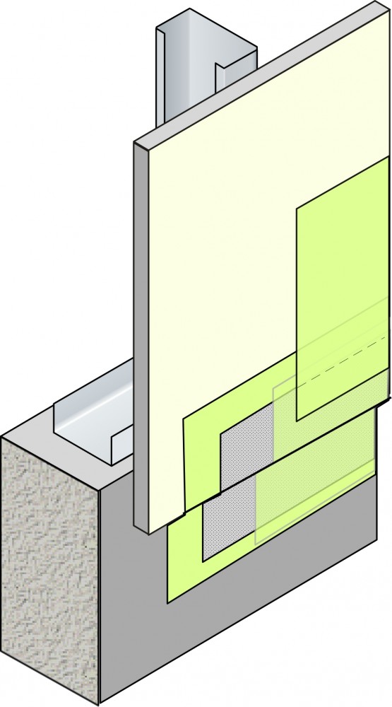
Transitions between dissimilar materials must be taken into account. For example, there is the transition from the sheathing of a building to its foundation. Air barrier products should be able to bond structurally to multiple types of substrates as well as being durable enough to bridge transitions where substrates may be out of plane with one another. Movement joints are included in buildings to account for anticipated expansion and contraction. As a result, the air barrier system should also be able to accommodate expansion and contraction.
These air barrier products are also going to be subject to thermal changes that will cause additional stress on the materials during the building's lifespan. The result is products such as kraft papers and building wraps may ultimately tear or pull away from the building. Other products like common joint tapes or self-adhered membranes may lose adhesion if not properly installed, causing discontinuity of the air barrier and potentially creating opportunities for moisture to intrude. If air barrier systems do not account for the same stresses the building will experience, then they may not only lose effectiveness, but can also actually create problems within the wall cavity that may not be detected until extensive damage has already been done.

The construction of an airtight building envelope greatly reduces the risk of moisture problems as a result of air leakage and condensation. However, airtight construction may be less capable of drying than air-porous construction in the case of water leakage or other unplanned circumstances that might allow water to enter the wall assembly.
Water is able to penetrate the building envelope through numerous means. For example, wind may drive rain through incidental cracks or holes in the building's cladding, or capillary action in porous materials, cracks, or holes may draw water toward the interior. Further, water vapor may be transported by air or diffusion that can condense on cold surfaces within the building envelope.
As mentioned, there are various products that may be classified as air barriers, but not all of them can be classified as water-resistive barriers (WRBs). In fact, the International Building Code (IBC), International Residential Code (IRC), and IECC have specific requirements that must be met for these products to qualify as both an air barrier as well as a water-resistive barrier.
In the case of air barriers, an individual product will be tested according to ASTM E2178, Standard Test Method for Air Permeance of Building Materials. Further, WRBs must meet ASTM D226, Standard Specification for Asphalt-Saturated Organic Felt Used in Roofing and Waterproofing, if they are to be considered waterproof.
Common tests, such as American Association of Textile Chemists and Colorists (AATCC) 127, Water Resistance: Hydrostatic Pressure Test, measure a product's ability to resist water penetration under adverse conditions, such as wind-driven rain, which is simulated by placing the product under hydrostatic pressure.
Traditionally, asphalt-saturated felt, kraft waterproof building paper, or building wraps have been used as the moisture protection component of wall construction. Installing these types of barriers usually involve shingle-style lapping and mechanical fastening to the sheathing with nails, screws, or staples. While these installation methods are common, because they disrupt the continuity of the air and water-resistive barrier, they actually provide opportunities for air leakage and moisture intrusion.
The best choice for an air and water-resistive barrier is one that meets a number of durability requirements and is able to resist wind and rain loads. Common criteria to look for include:
- resistance to puncture, pests, and low-sustained negative pressure from building stack effect and HVAC fan effect;
- ability to withstand stress from thermal and moisture movement of building materials and stress from building creep; and
- resistance to mold growth and abrasion.
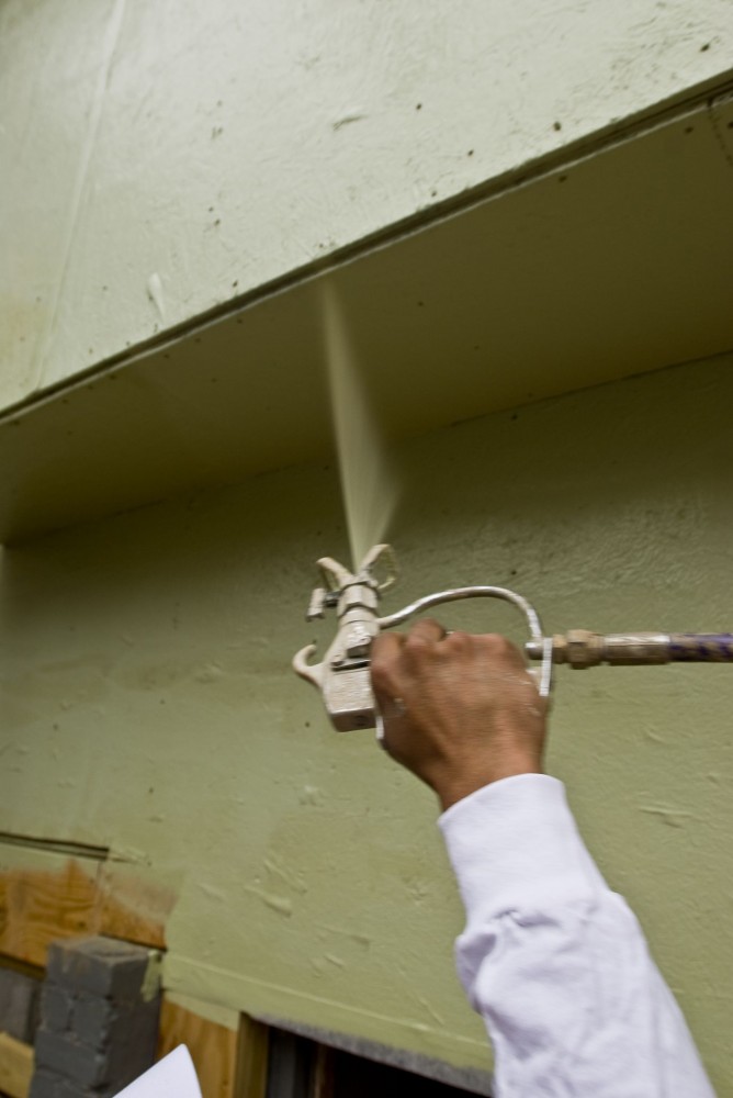
Fluid-applied barriers are gaining popularity in both commercial and residential construction due to their ability to form a full monolithic barrier, as well as their durability and ease of application compared to a traditional wrap or paper product. Many of these products act as both an air barrier and a water-resistive barrier.

Fluid-applied barriers are generally rolled or sprayed onto sheathing or concrete masonry unit (CMU) backup and fully adhere, becoming part of the structural wall. Some manufacturers use adhesion testing, such as ASTM C297, Standard Test Method for Flatwise Tensile Strength of Sandwich Constructions, to verify a full bond between the barrier and the substrate. It is often found the adhesion may actually exceed the strength of the substrate itself. However, this is not the case with paper-type products where material may tear or blow off the building, or with self-adhered membranes where a loss of adhesion may cause edge peeling or a loss of the barrier altogether.
As fluid-applied barriers are initially in liquid form, there is no lapping of materials that can create discontinuity of the barrier. Once a fluid-applied barrier is completely installed on a building's wall, the material acts as a single monolithic barrier. Fasteners such as nails, screws, and staples are not needed to apply fluid-applied barriers, so additional holes where rain can enter are less of a concern. Also, because fluid-applied barriers may be rolled or sprayed, the possibility of installation error is greatly reduced. Proper installation of paper-type products and self-adhered membranes frequently require cutting, folding, and use of special tools and accessories. Improper installation of these barriers can be costly and time-consuming to correct; all too often, these important details may be ignored altogether.
Conclusion
Plenty of research has been done to show the advantages of continuous insulation and air barriers. The inclusion of these elements in new construction should help enhance the overall energy efficiency of buildings and allow owners to realize energy cost savings as well. For design professionals, however, the task of creating an energy-efficient building may be just as difficult. New products and new resources are being developed every day to make this task easier, but in the meantime, the key point to remember is with both continuous insulation, as well as continuous air barriers, the details must be carefully considered to realize maximum energy efficiency.
Notes
1 For more, see U.S. Department of Energy (DOE) 2008, Buildings Energy Data Book. This resource was prepared for DOE's Office of Energy Efficiency and Renewable Energy (EERE) by D&R International. (back to top)
2 For more, see "Thermal Performance of Steel-framed Walls," by E. Barbour, J. Godgrow, and J.E. Christian, published by the national Association of Home Builders (NAHB) Research Center in 1994. (back to top)
3 See Morrison Hershfield's "Energy Conservation Benefits of Air Barriers–StoGuard: The Effect on Energy Conservation," by Chris Norris. (back to top)
4 See G. Finch et al.'s "Thermal Bridging of Masonry Veneer Claddings and Energy Code Compliance." The proceedings are taken from 12th Canadian Masonry Symposium, held in Vancouver, B.C. in 2013. (back to top)
5 See the Morrison Hershfield report, 1365-RP, "Thermal Performance of Building Envelope Details for Mid- and High-rise Buildings." (back to top)
John Chamberlin is product manager for StoGuard and StoEnergy Guard at Sto Corp; these divisions are focused on heat, air, and moisture management within the building envelope. Prior to this position, he served as product manager for StoCoatings and as associate product manager for StoPowerwall and StoQuik Silver. Chamberlin earned a Master's in Business Administration at Atlanta's Emory University and is a graduate of the University of Tennessee, with a Bachelor of Science degree in Marketing. He can be reached by e-mail at jchamberlin@stocorp.com.
![]()
Source: https://www.constructionspecifier.com/detailing-masonry-and-frame-walls-with-continuous-insulation-and-air-barriers/